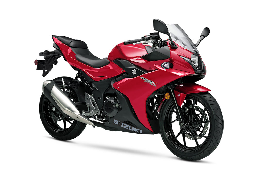
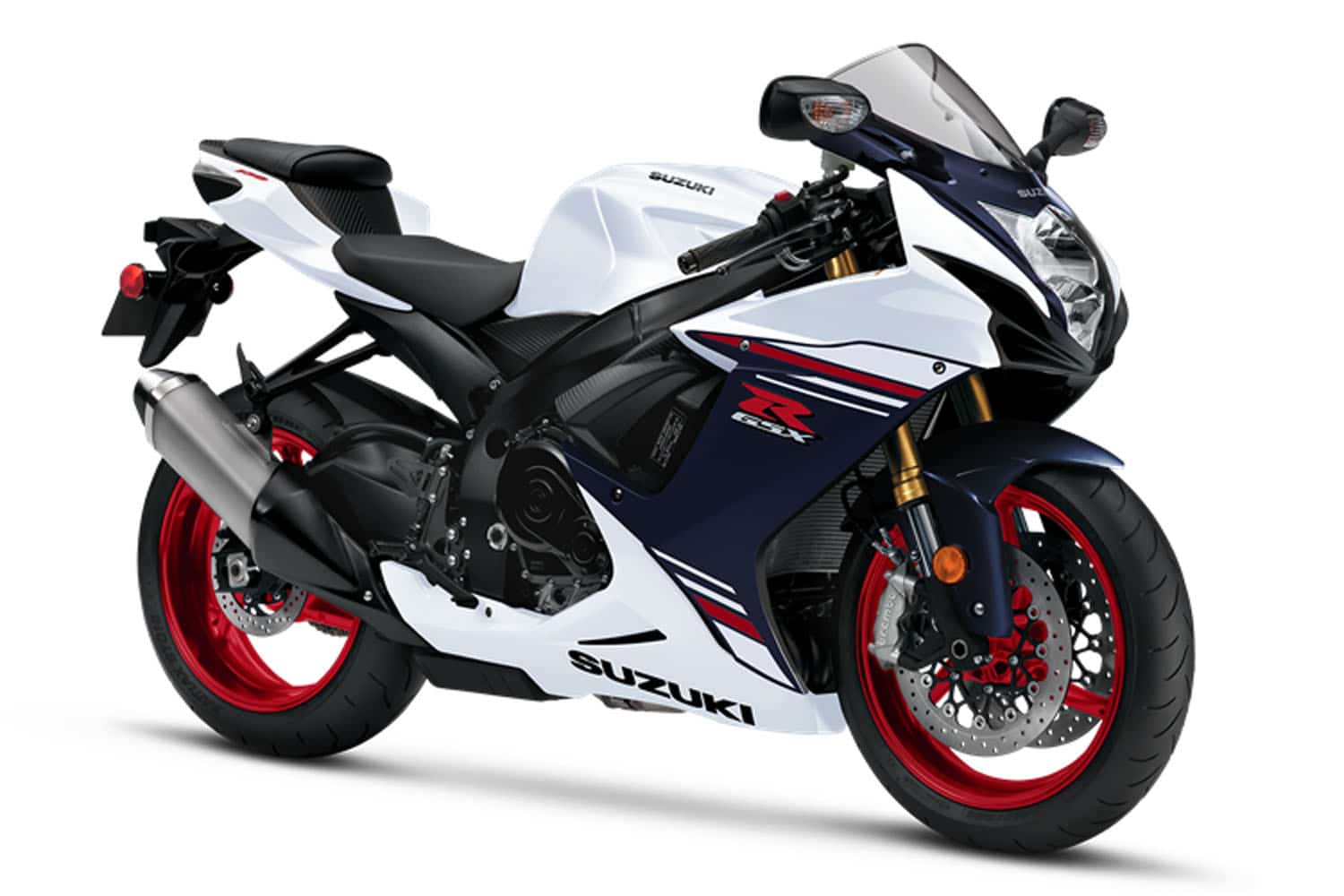
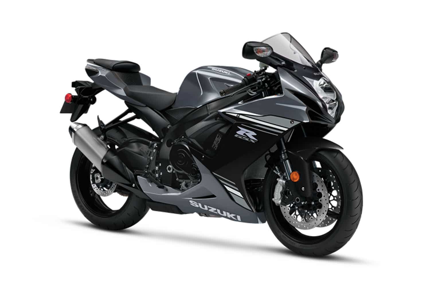
Service Manual for 2020 Suzuki GSX250R motorcycles. Service Manual, a great reference for the repair and maintenance.
If you’re looking to fix your motorcycle yourself, a service manual specific to your motorcycle model is an invaluable resource.
Ensure you have the correct service manual for your motorcycle’s make, model, and year. You can usually find these manuals online through official manufacturer websites, third-party publishers, or sometimes they’re available for purchase in physical form.
Service Manual, fix motorcycle yourself with a repair manual. Content 2020 Suzuki GSX250R Service Manual Service Manual.
Familiarize yourself with the manual’s layout and sections. It typically includes sections on maintenance procedures, troubleshooting, repair instructions, diagrams, and specifications.
Diagnose the issue with your motorcycle. Use the troubleshooting section of the manual to help identify potential causes based on symptoms.
The manual will provide step-by-step instructions for various repairs and maintenance tasks. These instructions will include details on tools needed, parts required, and the exact procedures to follow. Make sure to read through these instructions thoroughly before starting any work.
Follow the manual’s instructions carefully. Take your time and proceed step by step. Be cautious, especially when dealing with critical components like the engine, brakes, or electrical systems.
2020 Suzuki GSX250R Table of Contents
General Information
General precautions
Serial number location
Fuel, oil and engine coolant recommendation
Break-in procedures
Cylinder Identification
Information labels
Specifications
Country or area
Periodic Maintenance
Periodic maintenance schedule
Maintenance and tune-up procedures
Compression pressure check
Oil pressure check
Engine
Engine Removal and Installation
Crankshaft / Cylinder Head
Cylinder / Piston
Clutch
Engine Lubrication System
Starter system / Signal generator
Generator
Gearshift Linkage
Crankcase / Transmission / Crankshaft / Conrod
Fuel Injection / Air intake
FI System Technical Features
Intake Air System
Parts Location
Diagram
Wiring Diagram
Self-Diagnosis Function
Fail-Safe Function
FI System Troubleshooting
Fuel System
Throttle Body and STV Actuator
Sensors
Cooling and Lube system
Cooling Circuit
Engine Coolant
Radiator and Water Hoses
Cooling FanCooling Fan Thermo-Switch
Engine Coolant Temperature Gauge
Thermostat
Water Pump
Lubrication System
Chassis
Exterior Parts
Front Wheel
Front Fork
Steering
Rear Wheel
Rear Suspension
Front Brake
Rear Brake
Tire and Wheel
Electrical System
Cautions in Servicing
Location of Electrical Components
Charging System
Starter System and Side-Stand / Ignition
Interlock System
Ignition System
Combination Meter
Lamps
Switches
Relay
Battery
Servicing Information
Troubleshooting
Wiring Diagram
Wire Harness, Cable and Hose Routing
Fuel Tank Set-up
Cowling Set-up
Heat Shield Set-up
Side-stand Set-up
Gearshift Pedal Set-up
Fairing and Frame Cover Set-up
Special Tools
Tightening Torque
Service Data
Emission Control Information
Fuel Injection System
Evaporative Emission Control System
Canister Hose Routing
Evaporative Emission Control System Inspection
Diagram
Hose Routing
System Inspection
Wiring Diagram

